Overview
The CBFEM method combines the advantages of general finite element analysis with the standard component method. Stresses and internal forces from the finite element model are used to verify all connection components against Canadian standards CSA S16-14 and CSA A23.3.
Steel Plate Code-Checks
The equivalent stress (HMH, von Mises) and plastic strain are calculated for each plate. When the yield strength, multiplied by the resistance factor for structural steel (0.9, editable in Code setup), is reached on the bilinear material diagram, the equivalent plastic strain check is triggered. The plastic strain limit of 5% follows the guidance in Eurocode EN 1993-1-5 and is editable in Code setup. Each plate element is divided into five layers and elastic or plastic behavior is assessed in each. The program reports the worst result across all layers.
Weld Code-Checks
Fillet welds are assessed according to CSA S16-14, Chapter 13. Complete joint penetration groove welds are assumed to have the same strength as the base metal and are not checked separately.
Fillet Welds
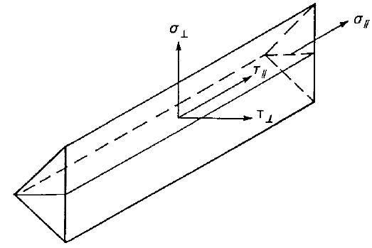
Resistance for direct shear and tension or compression induced shear is assessed according to CSA S16-14, Clause 13.13.2.2. The resistance depends on the weld throat area, the electrode classification number, and the angle between the weld axis and the direction of the applied force.
Bolt Code-Checks
Forces in bolts, including prying forces, are determined by finite element analysis. Bolt resistances are verified against CSA S16, Chapter 13.
Tensile Resistance
Tensile resistance of a bolt is assessed according to Clause 13.12.1.3. The resistance is a function of the resistance factor for bolts, the bolt cross-sectional area, and the specified minimum tensile strength.
Shear Resistance
Shear resistance is assessed per Clause 13.12.1.2. Each shear plane is checked separately. Where bolt threads are intercepted by a shear plane, the shear resistance is reduced to 70% of the full value.
Combined Tension and Shear
Bolts loaded by combined tension and shear are assessed using the circular interaction equation in Clause 13.12.1.4.
Bearing Resistance
Bearing resistance developed at the bolt in shear is assessed according to Clause 13.12.1.2. Reduced values apply for slotted holes loaded perpendicular to the slot.
Hole Tear-Out
Tear-out resistance is checked for individual bolts according to Clause 13.11, based on the gross area in shear and the material strengths.
Slip-Critical Connections
Slip resistance is assessed according to Clause 13.12.2. Reduced values apply for slotted holes. Bolts in combined shear and tension must satisfy an additional interaction requirement.
Concrete Block Code-Checks
The concrete below the base plate is modeled using a Winkler subsoil with uniform stiffness. The average contact stress at the loaded area is used for the compression check.
Concrete in Compression
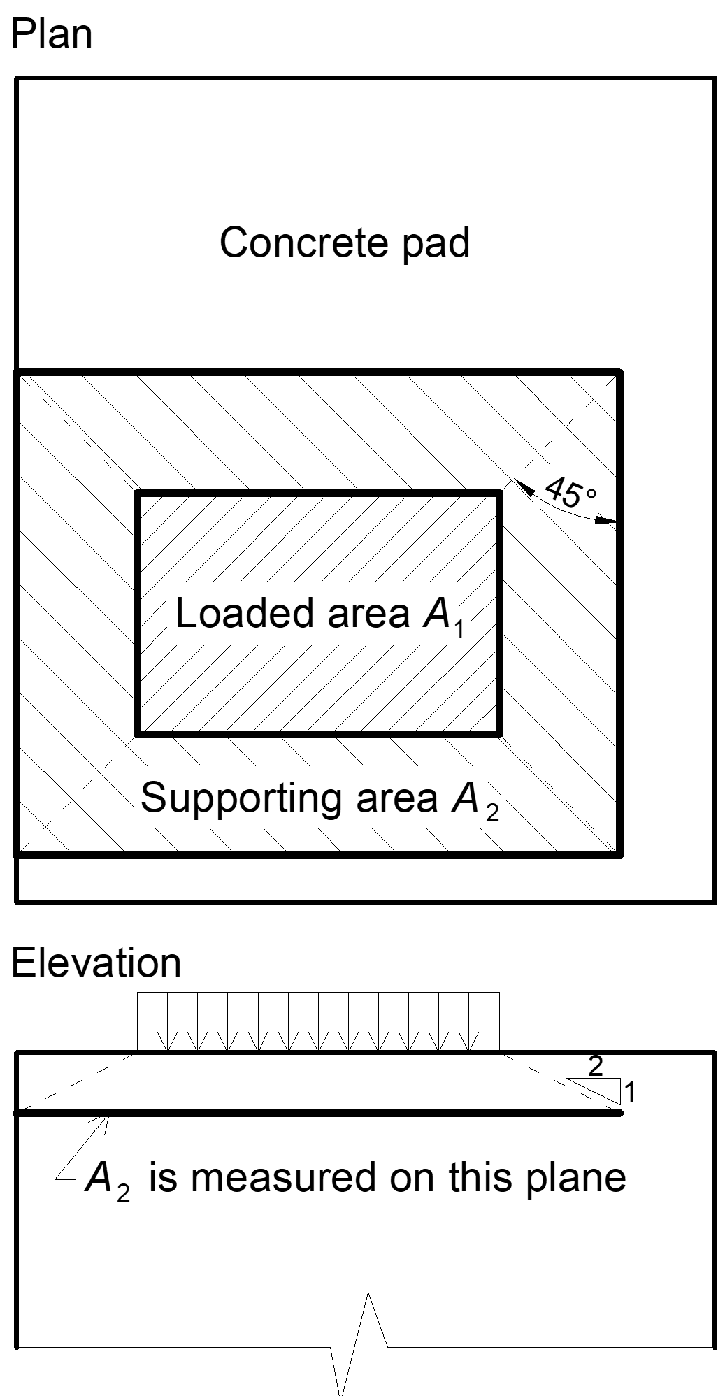
The design bearing strength in compression is determined in accordance with CSA S16-14, Clause 25.3.1, and CSA A23.3, Clause 10.8. When the concrete supporting area is larger than the base plate, the bearing strength is increased by the square root of the area ratio, subject to an upper limit.
Transfer of Shear Forces
Shear loads are transferred through one of three options: shear lug, friction, or anchor bolts. These options cannot be combined. Where shear lugs are used, concrete bearing is not checked by the software and must be verified separately. Where anchor bolts are used, each anchor is assessed according to CSA A23.3.